horn

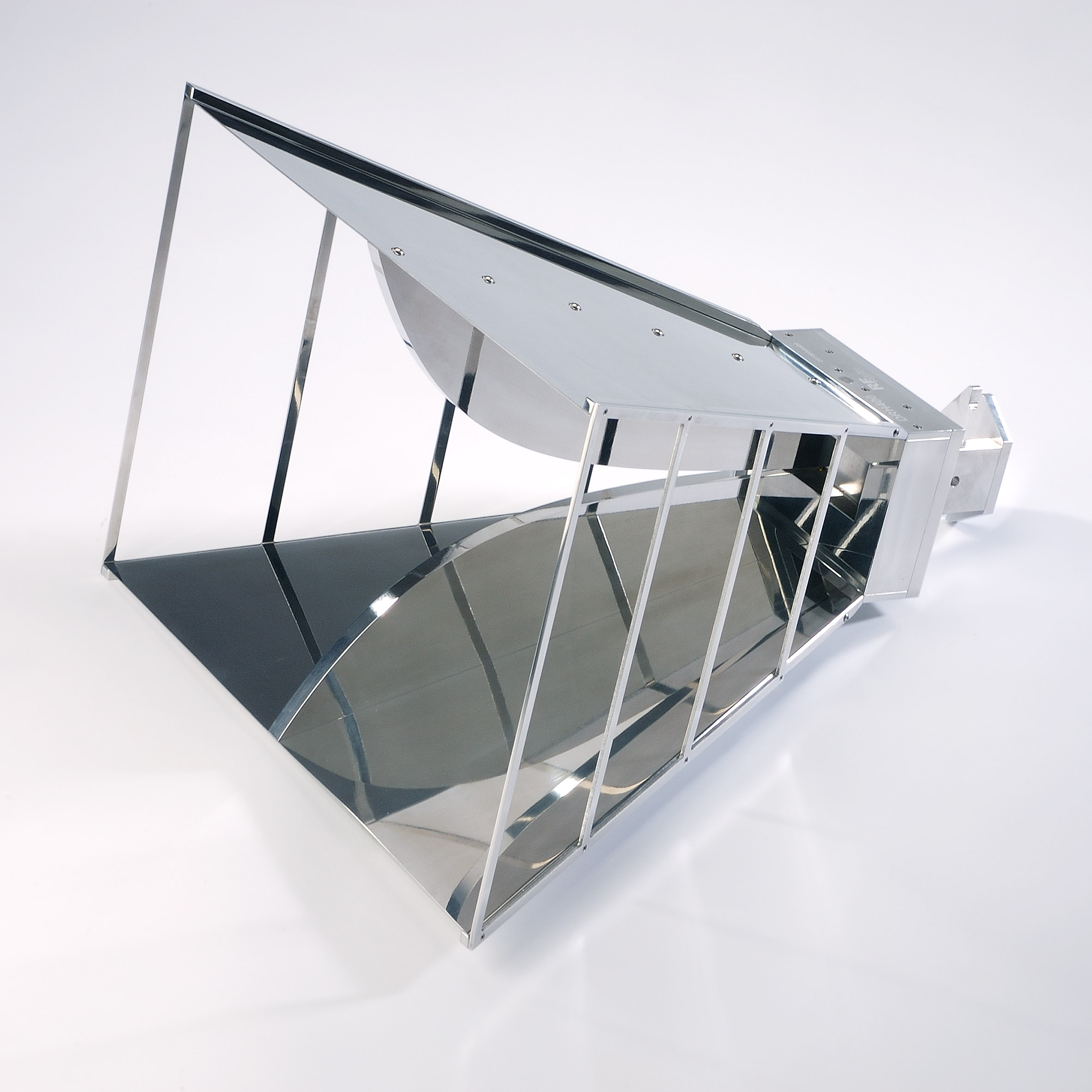
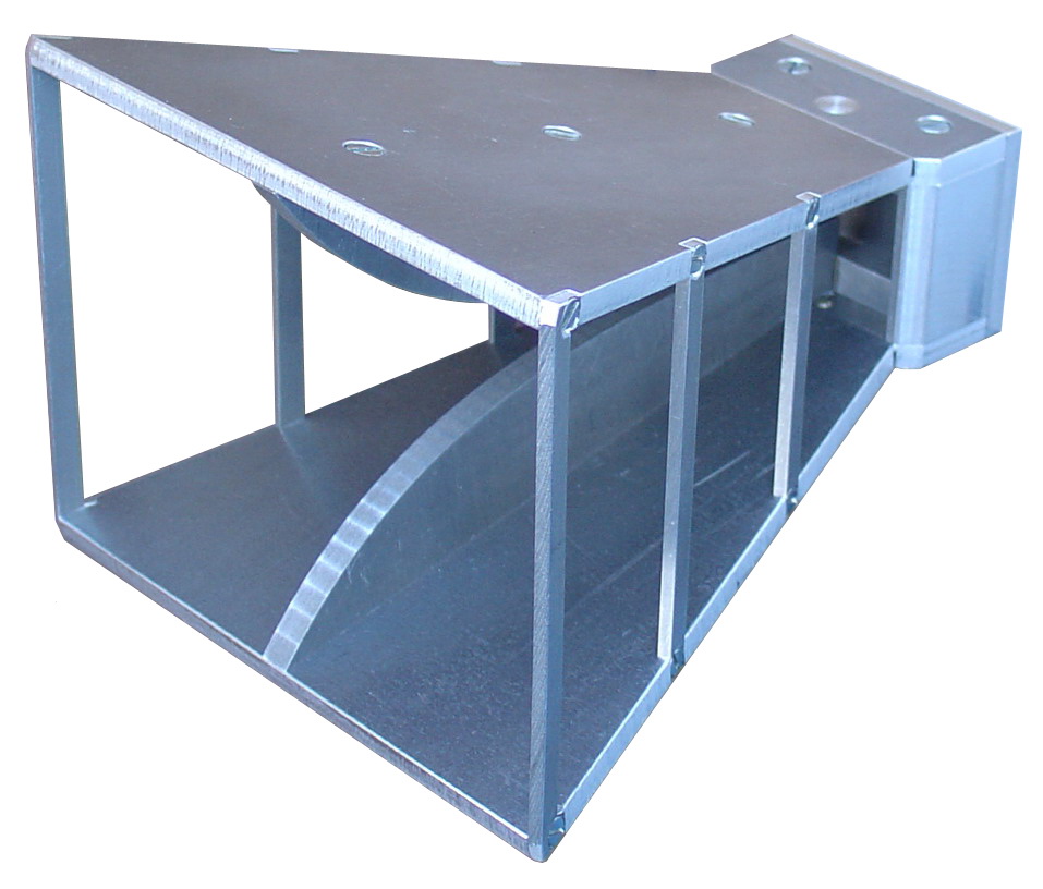
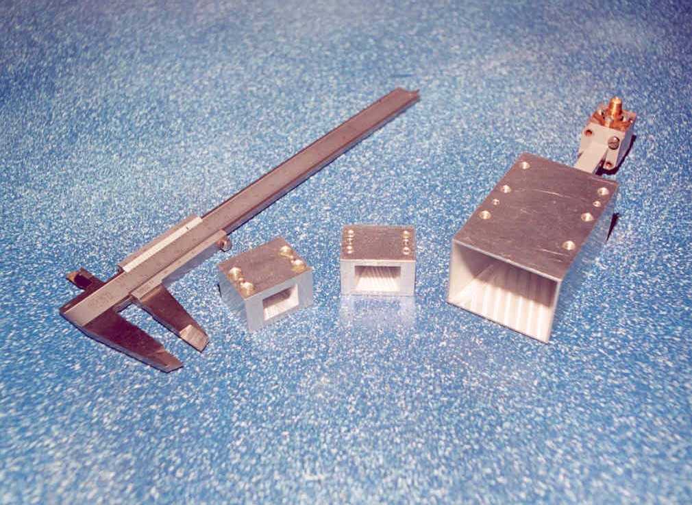
Horn antennas are very useful antennas fore wide range of frequencies starting approximately from houndreds of MHz. They can be designed as standards for measurements of gain of other antennas. Therefore there are very often used as a sets of antennars of standard gain.

For theory see:

Orfanidis, S: Electromagnetic Waves and Antennas, 2004-10, chapter 14 http://eceweb1.rutgers.edu/~orfanidi/ewa/ch19.pdf
Kraus, J.D., Marchefka. R.J.: Antennas for all Applications, McGraw-Hill, 2003, chapter 9 (Slot, Patch and Horn Antennas)

Horn antenna introduces a proper profile, which transforms electromagnetic energy of the guided wave into open space. To analyze such antenna, we usually use the principle, that we obtain the same radiation (or nearly the same) only from the distribution of the field in the aperture. In this case, the forward radiation will be calculated with very small deviation from reality. But the backward radiation is invisible in this case, because we did not calculate the part current which overtakes the edges of the horn and creates the possibility for back radiation. It is always necessary to keep in minds, that current and its distribution over the whole radiating structure is the real original source for radiation.

Simulations:

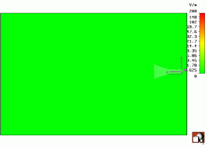
Horn_absE_animace This animation shows animation of electric field radiated by horn antenna where we can observe formation of spherical waves.
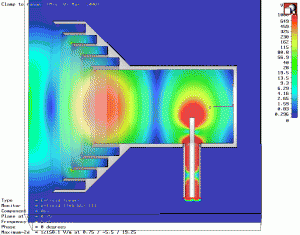
 corrugated_horn_Eabs_rez_x=0

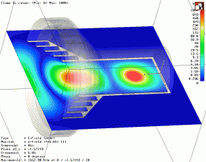
There are different profiles, that can create the transformation of the guided wave (see end of coaxial cable and short coupling dipole inside the structure) along wider and wider structure. In this proces, the impedance of the waveguide is transformed into open area. Of course, for fabrication there are some simplification. We can see some of the parasitic reflections from abrupt transmission and from the open end of the horn structure. So called “corrugated” horn in the visualization uses the structure with filter that blocks the current from overtaking the edges. The better results, namely the backward radiation can be achieved in this case. “Corrugating” means the stepped transformation from the waveguide in the aperture. This type of the horn has better matching and polarization purity. When we concentrate to watch the video carefully, we are able accept that wavelengths inside the waveguide is longer and getting shorter when approaching to the aperture. This is direct evidence the wavelength inside the structure that has critical frequency (it means that it can propagate) different from zero.

corrugated_horn_Eabs_rez_y=0 The same as above, but now electric field in the H plane is shown.

Gallery: