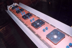
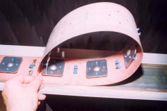
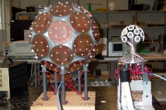
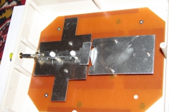
Microstrip patch antennas are low-profile antennas popular for higher frequencies (>1 GHz). Single radiating element has gain of around 8 dBi and they can be easily arranged into arrays. On the other hand, their bandwidth is limited.
For theory see:
Orphanids, S: Electromagnetic Waves and Antennas, 2004-10, chapter 14: http://www.ece.rutgers.edu/~orfanidi/ewa/ch19.pdf
Kraus, J.D., Marhefka, R.J.: Antennas for all applications, Mc Graw Hill 2005, chapter: Slot, patch and horn antennas (9)
Simulations - linearly polarized rectangular patch antenna:
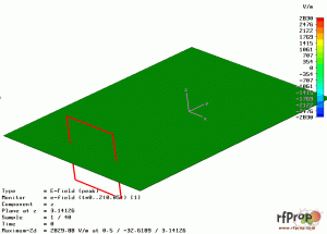 |
Rectangular patch antenna fed by microstrip line - animation of the vertical component of the electric field (dominant mode). The antenna is not perfecly matched, note standing waves at the feeding line |
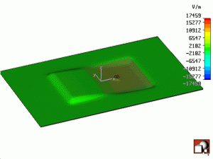 |
Rectangular patch antenna fed by coaxial line - animation of the vertical component of the electric field (dominant mode). |
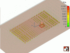 |
As above but now the fully vector E-field is shown. Note the fringing field at the shorter (radiating) edges. |
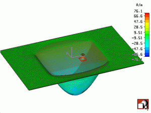 |
Animation of the magnetic field which is in turn responsible for surface current density, shown below. |
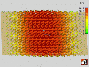 |
Surface current density at the rectangular patch of a dominant mode of operation. |
Simulations - circularly polarized patch antenna:
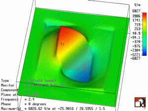 |
One possibility of creating circular polarization is to cut two corners of square patch. In this manner, two orthogonal modes with proper phase shift is employed. This animation shows rotating electric field (Ez magnitude) below the patch. |
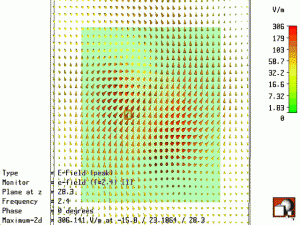 |
The rotating electric field above the circularly polarized patch |
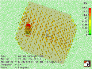 |
Surface current flowing at the circularly polarized patch |
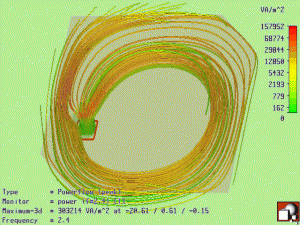 |
Power flow (Poynting vector) for the circularly polarized patch |
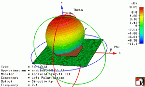 |
Radiation pattern (LHC) of the circularly polarized patch |


