Slot antennas can be basically cut out of whatever surface they are to be mounted on and have roughly omnidirectional pattern. Slots are usually used in array as we will see below.
For theory see:
Orphanids, S: Electromagnetic Waves and Antennas, 2004-10, chapter 14: http://www.ece.rutgers.edu/~orfanidi/ewa/ch20.pdf
Kraus, J.D., Marhefka, R.J.: Antennas for all applications, Mc Graw Hill 2003, chapter: Slot, Patch and Horn antennas (9)
Simulations - Slot antenna:
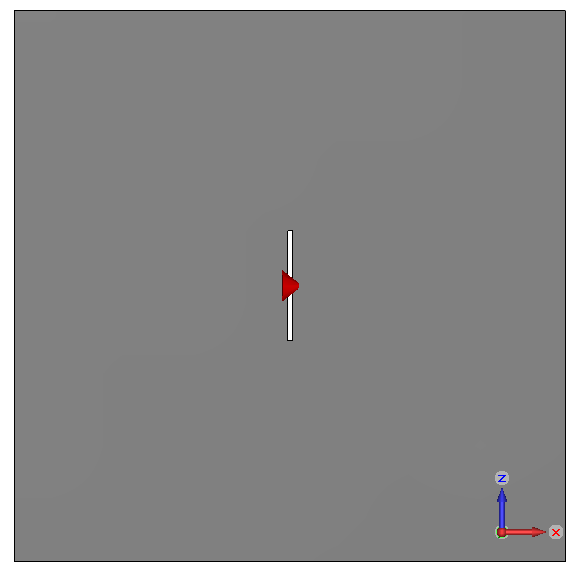 |
Desk with thin λ/2 slot cutted out. The slot is fed in the middle by a voltage gap. |
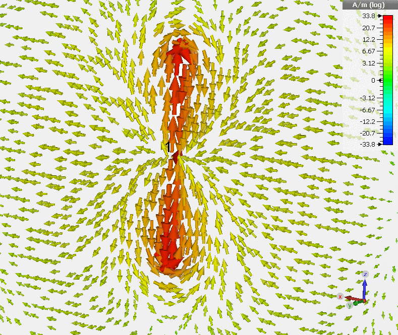 |
Distribution of electric current density flowing along the slot. Note that the vertical (y) components cancel out and only horizontal (x) component is effective in radiation. Polarization of the field may be thus deduced. |
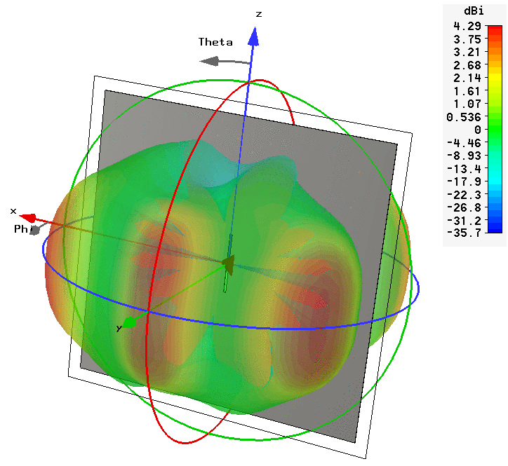 |
Radiation pattern of the slot antenna. It resembles pattern of a dipole but finite-sized desk is responsible for diffractions. |
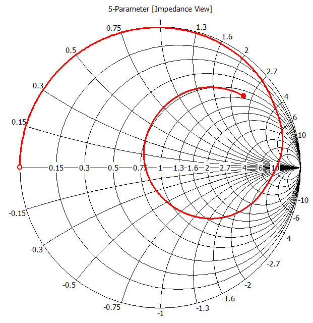 |
Input impedance of a slot antenna. At zero frequency it behaves as a short circuit, then becoming inductive and it finally comes to resonance having high resistance (around 500Ω) as follows from Babinet principle. |
Simulations - Slotted waveguide array:
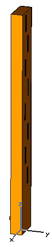 |
Rectangular waveguide is shorted at both ends, thus a resonator with given field/current distribution is obtained. Slots are cutted out at proper places (where the surface current is in-phase) so an array is arranged. |
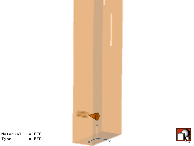 |
The waveguide is fed by an electric probe. |
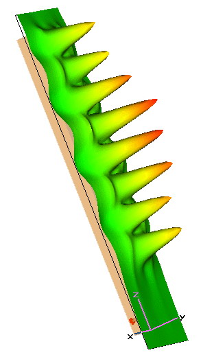 |
Distribution of electric field just above the slots. We can see that the field intensity varies (it depends on the slot offset from center) and is lower at the ends. This is because of eliminitaing the side lobes. |
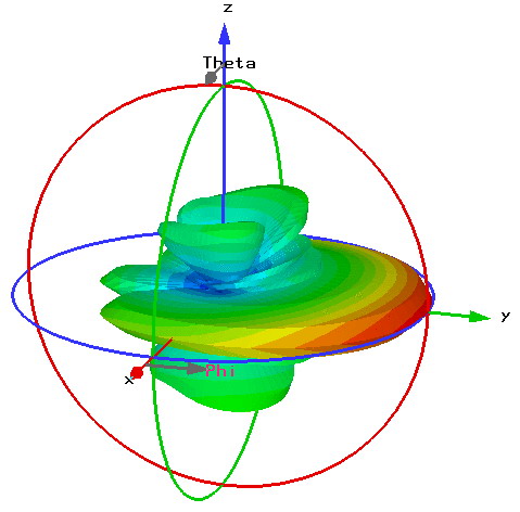 |
Radiation pattern of the array. Since the radiation pattern is basically the Fourier transform of the source distribution (see above), the pattern is narrow in vertical plane and broad in horizontal plane. Sector beam is constructed in this way. |
Gallery:


